38 iic pin labels in arduino mega are
arduino mega - Confused between SPI and I2C for SSD1306 ... manufactures are terrible about printing the right labels on those interface pins. i've seen SPI MOSI labeled: MOSI / SPI / DO / SDI / SDA / AD / A0 and DC; some of those aren't even close! there's only 2 wires, so that's a I2C. try flipping the pins if it doesn't work; ive seen them labeled backwards too. - dandavis. Character I2C LCD with Arduino Tutorial (8 Examples) This library comes pre-installed with the Arduino IDE. To install this library, go to Tools > Manage Libraries (Ctrl + Shift + I on Windows) in the Arduino IDE. The Library Manager will open and update the list of installed libraries. Now search for 'liquidcrystal_i2c' and look for the library by Frank de Brabander.
Arduino Nano Pinout, Specifications, Features, Datasheet ... To get it started with Arduino Uno board and blink the built-in LED, load the example code by selecting Files>Examples>Basics>Blink. Once the example code (also shown below) is loaded into your IDE, click on the 'upload' button given on the top bar. Once the upload is finished, you should see the Arduino's built-in LED blinking.

Iic pin labels in arduino mega are
Interface I2C 16x2 LCD with Arduino Uno (Just 4 wires ... After soldering connect the I2C Module to Arduino Uno. Arduino Uno I2C module. Analog Pin 4 - SDA. Analog pin 5 - SCL. 5V - Vcc. GND - GND. Connect the Arduino to computer. Next open Serial monitor from the icon on top right corner of Arduino IDE. And set the baud rate as 9600. Please ensure the correct port. DFRduino M0 Mainboard (Arduino Compatible) - OpenHacks Label: Description: 1: USB: USB Power: 2: External Power: 7~12V: 3: Digital IO D0~D13: Digital IO D0~D13 (Leonardo Compatible) 4: Digital IO D24~D31: Digital IO D24~D31: 5: SPI Interface: D14, D15, D16 (Pin Multiplexing) 6: Analog A0~A5: Analog A0~A5 (D18~D23 Multiplexing) 7: MCU: NUC123LD4AN0: 8: Xbee Socket: Serial1, support wireless programming Using I2C SSD1306 OLED Display With Arduino - Electronics ... An Arduino, (Arduino Mega in this tutorial) Power source, Powerbank, Battery, or USB cable. Wires. The Circuit. The circuit is very simple. First, connect the GND with Arduino GND, VCC with 3.3V or 5V on Arduino, SCL with SCL, and finally SDA with SDA pin. Upload the code and power on the Arduino.
Iic pin labels in arduino mega are. Ultimate Guide to Arduino Mega 2560 Pinout, Specs & Schematic Arduino Mega 2560 has 54 digital input/output pins, where 16 pins are analog inputs, 14 are PWM pins, and 6 are hardware serial ports (UARTs). It has a crystal oscillator-16 MHz, a power jack, an ICSP header, a USB-B port, and a RESET button. Arduino Mega Pinout. Voltage Regulator -The voltage regulator converts the input voltage to 5V. How to use all io pins on mega/due in a ... - forum.arduino.cc Hi. I'm in the start up phase of a larger arduino project. My plan was before to produce my own PCB with microprocessor and all components needed on a single board. But now I'm instead thinking of using the standard arduino hardware and do a shield instead, the gain of this is much shorter development time and the ability to just upgrade the shield instead of all hardware. arduino mega interrupt pins arduino broches méga interruption [bannière AdRotate ="7″] Qu'est-ce qu'une interruption. Une interruption est une fonctionnalité des processeurs qui permet à l'utilisateur d'attirer l'attention des processeurs. Donc, si vous exécutez un morceau de code, ne faites que des calculs, Je termine que vous avez un matériel extérieur qui ... LCD-Blue-I2C - ArduinoInfo These type displays have the 4 pins in the right order to connect directly to the Yourduino RoboRED by a 4-pin cable. I2C LCD DISPLAY VERSION 2: Marked "Arduino-IIC-LCD GY-LCD-V1" NOTE: The wire connections are in a different order! See the labels on the PC Board. Example Software Sketch for 2 line 16 character Displays:
The Arduino AREF Pin : 6 Steps - Instructables If you have an Arduino Mega there is also a 2.56V reference voltage available which is activated with: analogReference (INTERNAL2V56); Finally - before settling on the results from your AREF pin, always calibrate the readings against a known good multimeter. Conclusion The AREF function gives you more flexibility with measuring analogue signals. Using a 20x4 I2C Character LCD display with Arduino Uno ... Since the display and the real-time clock are both I2C devices, they will be connected to the same pins on the Arduino. For the Arduino Uno, the I2C pins are located on Pin A5 (SCL) and A4 (SDA). This may differ on any of the other Arduino boards. Connect the components as shown in the schematics below; How many analog pins are used in Arduino Mega board? # ... Explanation: It has a lot of digital input/output in that 14 pins can be used as PWM output, 16 pins are analog inputs, a USB connection, a power jack, and a... I2C Communications Part 1 - Arduino to Arduino | DroneBot ... Use the two analog pins, A4 and A5, as shown in the table above. I2C Between 2 Arduino's For our first experiment we will hoo two Arduinos together and exchange data between them. One Arduino will be the master, the other will be the slave. I'm using two Arduino Unos, but you can substitute other Arduino's if you don't have two Unos.
Wire - Arduino Reference Description This library allows you to communicate with I2C/TWI devices. On the Arduino boards with the R3 layout (1.0 pinout), the SDA (data line) and SCL (clock line) are on the pin headers close to the AREF pin. The Arduino Due has two I2C/TWI interfaces SDA1 and SCL1 are near to the AREF pin and the additional one is on pins 20 and 21. Arduino Mega Pinout | Arduino Mega 2560 ... - Electronics Hub Apart from that, the layout of Arduino Mega is very much self-explanatory. I will discuss about the pins of Arduino Mega in the Arduino Mega Pinout Section. Technical Specifications of Arduino Mega. As Arduino Mega is based on ATmega2560 Microcontroller, the technical specifications of Arduino Mega are mostly related to the ATmega2560 MCU. Arduino Mega Tutorial - Pinout and Schematics. Mega 2560 ... Pin 22 - SS, Pin 23 - SCK, Pin 24 - MOSI, Pin 25 - MISO These pins are used for serial communication with SPI protocol for communication between 2 or more devices. SPI enable bit must be set to start communication with other devices. Arduino - LCD I2C | Arduino Tutorial In this Arduino LCD I2C tutorial, we will learn how to connect an LCD I2C (Liquid Crystal Display) to the Arduino board. LCDs are very popular and widely used in electronics projects for displaying information. There are many types of LCD. This tutorial takes LCD 16x2 (16 columns and 2 rows) as an example. The other LCDs are similar.
Why is the digital I/O in Arduino slow and what can be done about it? - CodeProject
Arduino Nano: Pinout, Wiring Diagram and Programming Digital Pins D0 - D13: Input/Output Pins: Can be used as input or output pins. 0V (low) and 5V (high) (0) Rx, (1) Tx: Serial: The pins are used to receive (Rx) and transmit (Tx) TTL serial data. 2, 3: External Interrupts: The pins are used to trigger an interrupt on a low value or a change in value, a rising or falling edge. 3, 5, 6, 9, 11: PWM

Arduino Nano Pinout | Search Results | Arduino, Robot arm, Arduino projects
SPI - Arduino Reference This library allows you to communicate with SPI devices, with the Arduino as the controller device. This library is bundled with every Arduino platform (avr, megaavr, mbed, samd, sam, arc32), so you do not need to install the library separately. To use this library #include

Complete newbie to Arduino and electronics. Was wondering if this is possible?
arduino-info - LCD-Blue-I2C But you can wire it directly yourself if needed: There are 4 pins on the display.. (see photo below) Top to bottom: GND - GND VCC - 5V SDA - ANALOG Pin 4 SCL - ANALOG pin 5 On most Arduino boards, SDA (data line) is on analog input pin 4, and SCL (clock line) is on analog input pin 5. On the Arduino Mega, SDA is digital pin 20 and SCL is 21.

Arduino Mega Pin Diagram Explanation - Pcb Circuits
Interfacing Arduino with BMP280 pressure and temperature ... Interfacing Arduino with BMP280 sensor circuit: Project circuit diagram is shown below. Note that the BMP280 module shown in the circuit diagram has a 3.3V regulator and level shifter. Generally, the BMP280 module has at least 4 pins because it can work in SPI mode or I2C mode. For the I2C mode we need 4 pins: VCC, GND, SDA and SCL where:
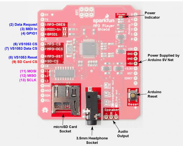
Audio Arduino shield for project
Arduino Mega Mega2560 I2C on pins A4 and A5 for Arduino ... Koepel December 23, 2017, 12:30pm #7. No, the I2C is fixed to the specific pins for a ATmega2560 microcontroller. I can think of two things, perhaps someone else can think of a third one. You could try a software I2C library on pin A4 and A5. Here is a list of those libraries: Arduino I2C libraries · Testato/SoftwareWire Wiki · GitHub.
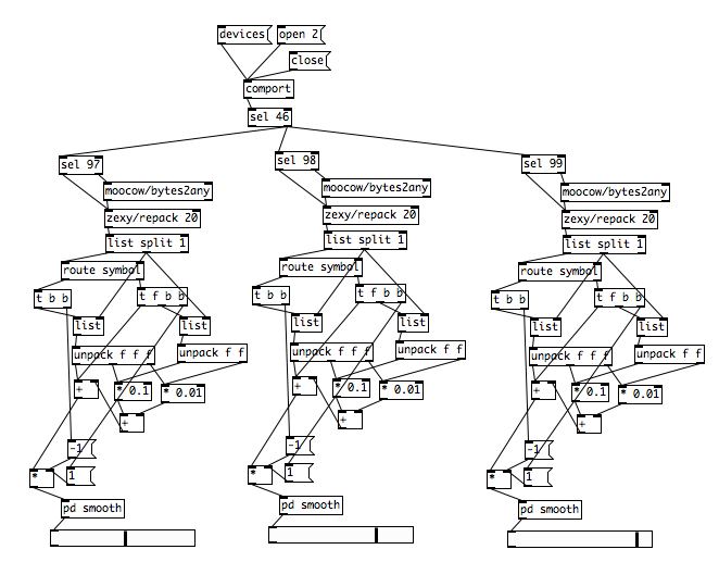
Arduino - Data Type | PURE DATA forum~
How to Connect a Serial LCD to an Arduino UNO : 4 Steps ... Step 1: Connect the Electronics 3 More Images I will use 4 colored jumper wires to make it easy. There are 4 pins on the UART labeled GND, VCC, SDA and SCL. Use the red wire to connect the VCC from the UART to the VCC on the Arduino Use the black wire to connect the GND from the UART to the GND on the Arduino
![Pin on Lintingan[dot]com](https://i.pinimg.com/736x/b5/28/62/b528626cae82d9852738b0c4f7a808d5--arduino-source-code.jpg)
Pin on Lintingan[dot]com
Arduino Mega Pinout Diagram - Use Arduino for Projects Arduino Mega Introduction: The Arduino Mega is a microcontroller board based on the ATmega1280 (datasheet). It has 54 digital input/output pins (of which 14 can be used as PWM outputs), 16 analog inputs, 4 UARTs (hardware serial ports), a 16 MHz crystal oscillator, a USB connection, a power jack, an ICSP header, and a reset button.
Digital iVision Labs!: 03/19/13
Labels · bahuri/YMFC-AL_ARDUINO_MEGA_2560 · GitHub This is a fork of Joop Brokkings amazing YMFC-AL arduino flight controller - Labels · bahuri/YMFC-AL_ARDUINO_MEGA_2560
Post a Comment for "38 iic pin labels in arduino mega are"